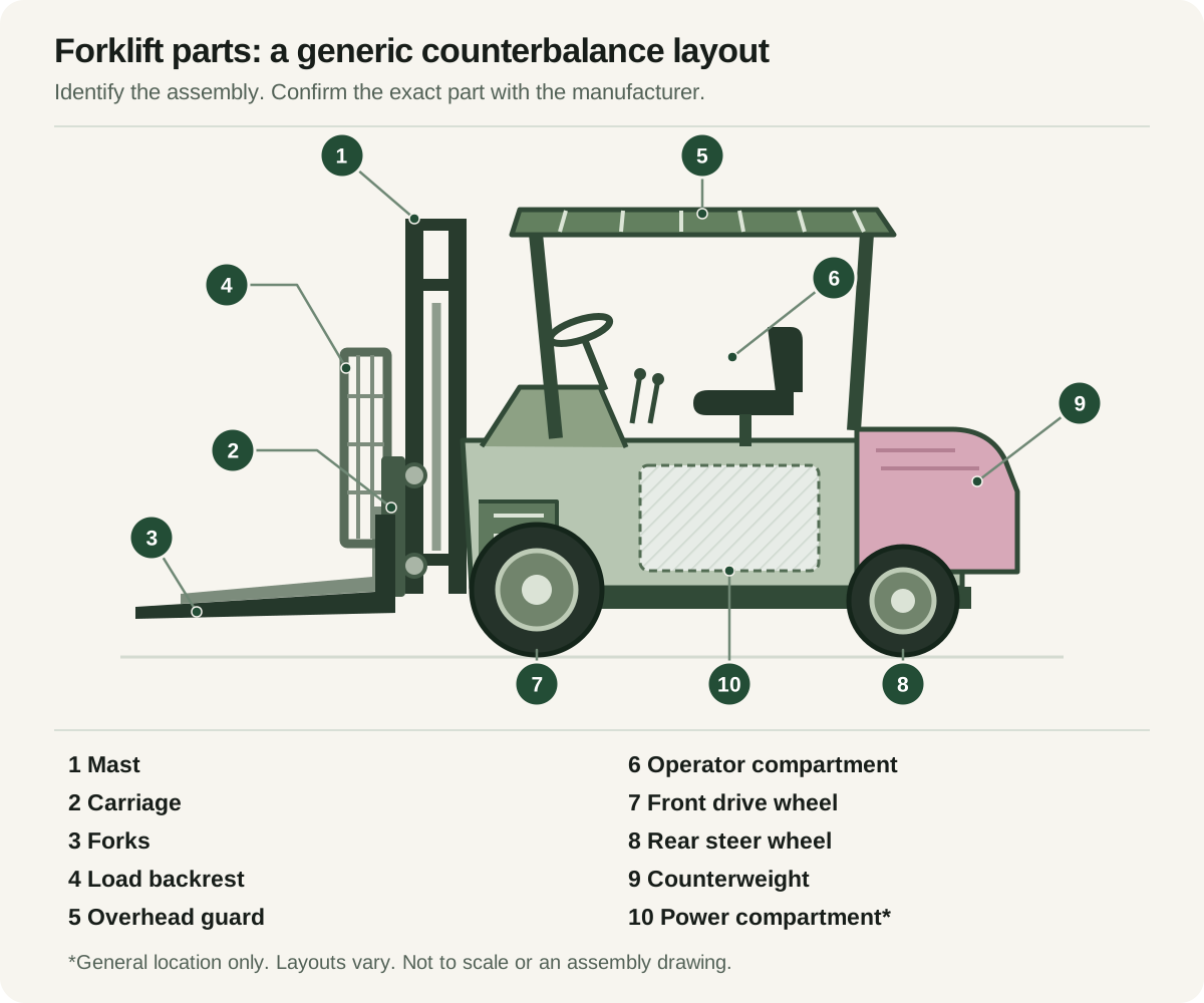
The main visible assemblies of a counterbalance forklift include the mast, carriage, forks, load backrest, overhead guard, operator compartment, wheels and counterweight. Use this generic diagram to describe a component. Use the manufacturer’s model- and serial-specific parts information to identify the replacement part; the drawing does not establish compatibility.
1–4: the lifting assembly
The mast (1) is the upright assembly that guides lifting movement. The carriage (2) travels with the lifting system and supports the forks or an attachment. Forks (3) support a suitable load from below. The load backrest (4), where fitted, extends above the carriage and helps reduce the possibility of material falling rearward. These are separate assemblies: a request for “the front lifting part” needs more identification before a supplier can locate the correct item.
5–6: the operator area and overhead guard
The overhead guard (5) is above the operator compartment (6), which contains the driving and load-handling controls. A guard offers protection against certain falling objects; it is not designed to withstand a falling load equal to the truck’s rated capacity. It also does not remove the need for correct load handling. The backrest is not a guarantee that an unstable load cannot fall. Guard and restraint arrangements must match the actual truck and its instructions.
7–9: wheels, steering and counterweight
The illustrated layout has front drive wheels (7), rear steer wheels (8) and a counterweight (9) behind the operator. This is a typical counterbalance arrangement, not a drawing of every forklift design. Three-wheel trucks, reach trucks and other equipment differ. The counterweight contributes to the machine’s balance; adding weight is not a valid way to increase its published capacity. Tyres and wheels must also match the approved configuration.
10: the power compartment and hidden components
The outlined power compartment (10) is a general location marker. A truck may use a battery and electric drive or an engine and fuel system, with components arranged differently by model. Hydraulic lift and tilt cylinders control different movements, while chains, hoses and other components may be partly hidden by the mast or body. A side-view illustration cannot identify their sizes, connection points, routing or service procedures.
Find the data plate before specifying equipment
The capacity plate is not assigned a fixed location in this diagram because its position varies. Locate it using the operator’s manual. Record the truck identity and capacity information for the fitted mast and attachments. When changing an attachment, ask the manufacturer or competent supplier to confirm compatibility and the applicable capacity information. A component that physically fits is not automatically suitable for the truck’s rated configuration.
Turn a part name into an accurate enquiry
Provide the make, model, serial number, relevant attachment identity and any readable part number. Describe the component’s location and the symptom without assuming which repair is needed. Clear photographs can help identify an assembly, but take them only from a safe position without reaching into machinery. Ask the supplier to confirm the correct catalogue reference, required installation work, availability and delivery. Safety-critical assessment and repair belong with qualified personnel.